System Draw / Wireless links
External wireless links
Wireless link planning: point to point, point to multipoint and mesh
Plan the outdoor wireless links that carry CCTV and security systems across a site: between buildings, out to the gatehouse, and to cameras on poles and fences where a cable run isn't practical.
Built for external links
The wireless devices in System Draw are for outdoor links that carry your security systems from one place to another. They are not for planning indoor Wi-Fi.
Point to point
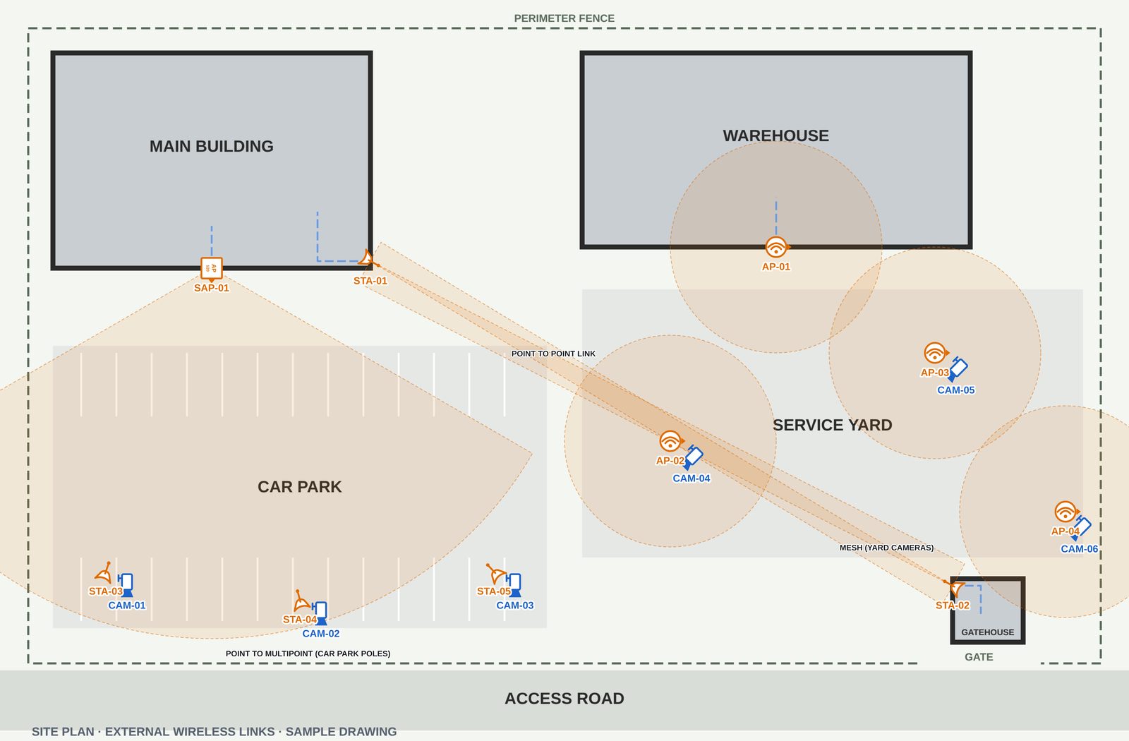
Link two buildings, or a building and a gatehouse, with a pair of wireless stations aimed at each other. Set each one's direction and range so the beam on the plan runs from end to end, and check the path for buildings and trees in the way.
Point to multipoint
Put a 120° sector base station on the building and a station at each camera pole or outbuilding it serves. The sector is drawn on the plan, so you can see that every remote end sits inside it.
Mesh
For cameras spread across a yard or along a fence, place mesh nodes with a 360° range and check that each node overlaps its neighbours, so the mesh has more than one path back.
Wireless devices
- Wireless AP: a base station or mesh node, with a directional or 360° range
- Wireless AP 120° sector: the base station for point to multipoint links
- Wireless station / CPE: the remote end of a point to point or point to multipoint link
IP addresses and the network schedule
Give every base station, station and mesh node its IP address, VLAN and switch port. Duplicate or mistyped addresses are flagged, and each radio appears in the network schedule with your CCTV and door access kit, so the whole site's addressing is on one sheet.
Cat5e runs, measured
Draw the Cat5e (or Cat6) runs from each radio to its PoE switch or injector, and on to the camera it serves. They are measured once the plan is to scale and listed in the cable schedule.
How it works
- Bring in the site planImport the site plan, or a picture of the site from above, and set the scale so link distances and cable runs are measured.
- Place the radiosAdd the base stations, stations and mesh nodes, aim them, and set their range to match the link.
- Export and sendExport a branded A3 or A4 PDF, or a PNG, with the device legend and cable schedule, ready for the quote or handover pack.
Try it free for 14 days
System Draw runs in Chrome or Edge on Windows and Mac. Your plans stay on your own computer.